| Exporting
and using Spice
netlists
in Microwave Office |
|
| Exporting
and using Spice
netlists
in Microwave Office |
|
|
|
|
In
CMS it is possible (from v.5.0) to save filter designs as PSpice netlists
for later import into a circuit simulator. To
demonstrate how to we now want to transfer the following CMS design
into a model which can be used in Microwave Office (MWO): |
|
|
|
1.
To create a PSpice netlist we simply select the Make PSpice Netlist
entry in the Tools drop-down menu. |
|
|
| 2. Then specify a name and save the spice netlist in the Netlists folder in the CMS installation directory. The P-Spice netlist for the filter in question is called MWO_test_filter and it gets the PSpice .cir extension. |
|
|
|
We
are now done with CMS and the rest goes on in MWO. |
| 3. For the purpose of this demo a new MWO project (CMS_Spice_Test) has been created: |
|
|
| 4. In Project Options in the project tree, enter the same frequency range as was used in CMS: |
|
|
|
5.
Right-click on Netlists in the project tree and select Import
Netlist... Then
browse to the Netlists folder in the CMS installation directory and
select the CMS_Spice_Test.cir file (usually located
in: C:\Program Files (x86)\Guided Wave Technology\CMS\Netlists). MWO
then imports the PSpice file |
| 6. Scrolling down to the bottom in the netlist it can be seen that the filter has been given the name MWO_Test_Filter, which is the name which we gave the netlist when creating it in CMS. |
|
|
|
7.
Next, right-click on Circuit Schematics in the project tree and
select New Schematic... In
the present case the schematic is called MWO_test_filter. |
| 8. Choose the Subcircuit button in the top menu or alternatively - select Add Subcircuit from the Draw fall-down menu: |
|
|
| Click OK to add a subcircuit element and place the sub-circuit on the schematic. |
|
|
|
The
subcircuit with all parameters is now visible in the schematic: |
|
|
| 9. Then add ports by choosing the port button in the top menu: |
|
|
| The
Netlist has now been imported into MWO. All couplings and other parameters
are now available for further treatment in MWO. |
|
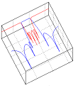
10.
To plot the filter characteristic in MWO we need to insert the plots:
|
|
|
| 11.
Then add a new measurement to the same graph and select S11 this time. |
|
12.
Everything is now ready for running the simulation. |
|
|
|
It
can be verified by comparison that the MWO generated plot is close to
identical to the original from CMS. By
selecting the Variable Browser entry in the View fall-down
menu, one can get an overview of all the available parameters in the
netlist model. Here one can also specify which parameters should be
available for further optimization etc. The
available parameters are:
|
| Final remarks to the netlist model |
|
The
couplings in the netlist model have been implemented using lumped
admittance inverters based on ideal inductors. An
inductor is a frequency dependent (physical) device, which used in
admittance inverters will give frequency dependent couplings. The netlist
model in ADS is therefore more physical as compared to the pure
mathematical model used in CMS, where couplings are 100% independent of
frequency. For
this reason differences will exist between CMS and the netlist model
especially when the bandwidth starts to increase and exceeds 10% relative
bandwidth. |
© 2017, Guided Wave Technology - All Rights Reserved