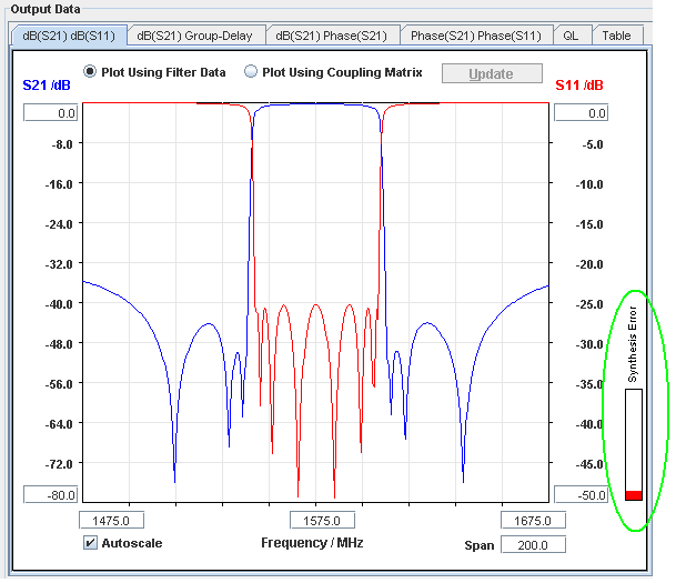
- The error indicator is a help to the user
- showing the possible quality of the synthesized
coupling matrix.
- A red bar shows the error level: A
large red area means that the error is also high.
- The error is calculated by comparing
the ideal characteristic as defined by the filter input parameters, to
the characteristic as calculated from the synthesized coupling matrix.
- The ideal characteristic is the one which is displayed when the
'Plot Using Filter Data' button is selected
- The characteristic, which the coupling matrix represents, is plotted
when the 'Plot Using Coupling Matrix' button' is selected.
The error is therefore the average difference (in dB) between these
two characteristics (only S21 is used to calculate the error).
- The error is only calculated in the
displayed frequency band. Changing the span may therefore also change
the synthesis error.
- The actual error is read out when the
mouse cursor is placed over the error bar.
- If a non-zero error results, the user
should select the 'Plot Using Coupling Matrix' button to see whether
or not this error is a problem.
- If the wanted characteristic differs
significantly from the synthesized characteristic (one or more
transmission zeroes may for example be missing), the topology matrix
has to be changed and/or the filter order needs to be increased (see Topology
Matrix).
- When the coupling matrix is manually
edited the error related to these changes is also displayed.
- The "dynamic range" of the
synthesizer is limited. This means that if S21 gets below -150 dB to
-200 dB there may be a difference between the ideal characteristic and
the characteristic as calculated from the coupling matrix. This error
is caused by numerical inaccuracies, and is therefore not necessarily
an error in the synthesized filter. Try to narrow in the frequency
span.
- The combination of very narrow
bandwidths (< 1 %) and large filter orders (N>10) may give rise
to numerical inaccuracies on the calculated couplings, which may
indicate false synthesis errors. At present the best fix to this
problem is either to decrease the filter order or increase the
bandwidth.
|