| Output Section - Coupling Matrix/Info |
|
| Output Section - Coupling Matrix/Info |
|
|
|
|
| Coupling Matrix: | |
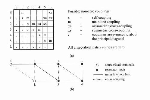
| A coupling matrix of the fully-canonical folded form is shown below | |
|
|
Folded
canonical network coupling matrix form - fifth degree example.
(a) Folded coupling matrix form. "s" and "xa" couplings are zero for symmetric characteristics. |
| Figure reprinted from [1] with permission from Dr. Cameron. | |
As
described in [1] and [2]
the above folded canonical network coupling matrix
has the following characteristics/advantages:
A wealth of information on filters and
coupling matrices may be found in [4]. |
|
| Normalization: | |
|
The coupling coefficients used in this software may be presented in three ways:
The normalized coupling coefficient between resonators i and j is denoted Mij and is related to the 'normal' or actual coupling coefficients by multiplication with the relative bandwidth, i.e. ripple bandwidth divided by center frequency, Kij=Mij*BW/f0 If coupling bandwidths are desired the entries of the coupling matrix outside the main diagonal need only to be multiplied by the ripple bandwidth 'BW'. In this case the coefficients will have dimension of frequency (e.g. MHz), Cij=Mij*BW When the coupling bandwidth option is selected the entries in the main diagonal (self couplings) represent the resonance frequencies of the resonators (see e.g. [4] and [5] for more info). Sometimes the external couplings (or Q) are also nice to know. These may be found from: Qe,S=1/(w*MS12) Where w=BW/f0. MS1 and MNL are often also denoted M01 and MNN+1 respectively. N is the filter order. 'MS1' refers to the input coupling value in row 'S' and column 1. The normalized source and load terminations - RS and RL - are unity in the Mij display mode due to the transformation by MS1 and MNL, respectively. |
|
| When a coupling matrix is stored in a text file the Mij format is always used. | |
© 2017, Guided Wave Technology - All Rights Reserved