| Input Section |
|
| The input parameters are explained
below. Most are self explanatory, but some of them need some extra
words. |
| Input Section |
|
| The input parameters are explained
below. Most are self explanatory, but some of them need some extra
words. |
 |
Filter
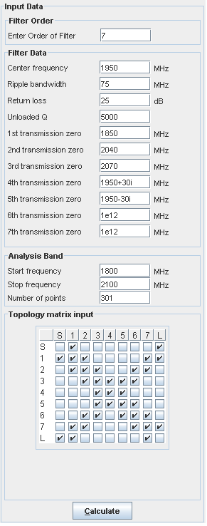
order: The order of the filter must be between 2 and 14. When the order is changed the "Return" button must be hit to update the remaining part of the input section. |
|
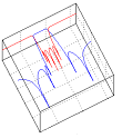
| Transmission
zeroes: For a N'th order filter - N finite transmissions zeroes can be specified. This is possible since coupling between input and output ports is allowed. A finite real transmission zero is often seen as a 'notch' or 'dip' in the amplitude transfer characteristic, but may not be seen in the filter transfer characteristic if the transmission zeroes are complex. The complex transmission zeroes may - if placed in the pass band - be seen in the time delay characteristic. A filter without finite transmission zeroes has all its zeroes placed at infinite frequencies. If - as an example - only two finite transmission zeroes exist in a 7'th order filter, the remaining 5 transmission zeroes must be placed at 'infinity'. Infinity' is represented by the frequency 1e12 MHz. All transmission zero entries - in the input form - must contain a value, either a finite or infinite (1e12) frequency. Complex finite frequencies are as mentioned allowed, but must always appear as complex conjugated pairs. If this is not fulfilled the transfer characteristic and coupling matrix will not be valid. In the example to the left 3 finite, 2
complex and 2 infinite transmission zeroes are present. |
||
| Analysis Band: | ||
| The start and stop frequencies define the frequency band, which are used for plotting the filter characteristics. The number of frequency points used in the calculations must be between 21 and 801. | ||
| Topology matrix: | ||
| The
topology matrix describes which couplings the filter designer will allow in a filter and
which are not allowed. In this way the filter designer defines the
"shape" - or topology - of the physical filter, e.g. if input
and output connectors are placed in the same end - or opposite. A 'checked' field in the matrix indicates a signal path - i.e. coupling - between two resonators and an 'un-checked' field indicates zero coupling. 'S' and 'L' denote input and output ports respectively. |
||
|
|
||
|
The 'Calculate' button may be activated by use of the 'Alt C' key combination. For more information and some examples - click here. |
||
© 2017, Guided Wave Technology - All Rights Reserved