Output Section - Stored Energy or QL
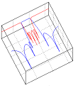

How much power a filter can handle before break-down occurs is dependent on factors like pressure, temperature, resonator geometry, unloaded Q, return loss, topology, frequency, signal dynamics (modulation, duty-cycle, prf) etc.
 
The stored energy of a resonator is proportional to the square of the peak electric field strength of the resonator.
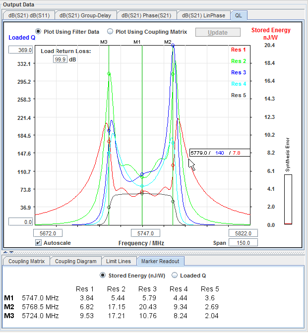
 
  • In CMS the stored energy (or equivalent - the loaded Q) for each resonator can be plotted versus frequency. 
    The calculated stored energy levels in CMS are normalized to 1 W applied at the input.
  • This feature allows the filter designer to optimize designs with respect to power handling.
  • It is possible to specify the load returnloss in the QL graph, whereby the axes values are scaled correspondingly. The values are scaled assuming worst case phase conditions between filter and load. When a return loss is entered in the
    text box the stored energy calculation is invoked by pressing the "Return" key on your keyboard (not the "Calculate" button in CMS).
  • The curve values can be read out by moving the mouse cursor around in the plot or by placing marker lines.
  • CMS pinpoints the resonator(s) where break-down will occur first and also the corresponding stored energy.
    This energy can easily be scaled to power levels other than 1W
 
Loaded Q and stored energy (10-9J/Watt) for each resonator in the filter.


 More information on power handling analysis of Rf filters can be found in GWT's Microwave Journal Article [6]  
 and in the CMS web site's example.
The graphs can be arranged by changing the values on the axes.

© 2017, Guided Wave Technology - All Rights Reserved